One weekend I spent a day capturing on video my adventure…..
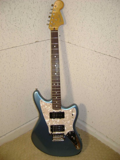
in modifying my brand new Fender Modern Player Marauder to install the Roland GK-KIT-GT3 permanently, internally in the guitar. Last year I wrote about my first venture into GK land and how I installed the Roland GK-3 external pickup on an Epiphone Dot semi-hollowbody guitar.

Per Roland’s product description:
This kit includes all parts for permanent installation of a GK-3 Divided Pickup into an electric guitar: a GK-3 Divided Pickup, circuit board, switches, power indicator LED, 13-pin connector, wiring and hardware. Professional installation is required.
- Divided guitar pickup for use with Roland V-Guitar System, GR-20 Guitar Synthesizer, or BOSS GK Effect Pedals
- 3-position switching between divided pickup, natural bass pickup, or mix of both
- Mounts on any electric or steel-stringed acoustic guitar
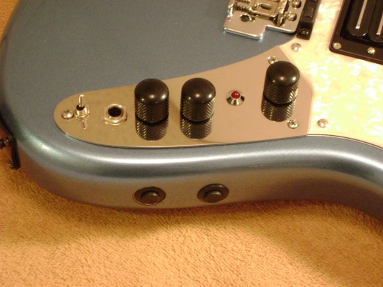
UPDATE: Since the above picture was taken the S1 and S2 buttons have been recessed so they are below the surface of the guitar to avoid accidentally making a change mid performance!
First here is my video….wow, I surprised myself….I am actually getting a little better at camcorder action and iMovie editing….and then I have transcribed below my 40 steps from my spiral notebook to install this unit. Due to YouTube’s rules, I had to split this into two parts to stay under their “10 minute rule”:
Part 1
Part 2
Since this is what I did specifically for my Fender Modern Player Marauder all of the steps might not apply to your guitar if it is not a Marauder or you decide to wire things differently than I did. By the way, there is a great resource on all things related to V-guitar and DIY guitar projects at the V-guitar user forums site at www.vguitarforums.com.
- Plan the layout.
- Disassemble guitar. (be careful not to scratch or damage anything!)
- Mask the guitar as needed to protect it while you are working on it.
- Mark the locations for the GK components.
- Remove the volume and tone pots and guitar cord jack from the metal face plate.
- Drill test holes in scrap material.
- Verify the fit of all GK parts in the scrap material.
- Adjust hole sizes if necessary.
- Drill the metal face plate per your planned hole locations.
- Drill the S1 and S2 switch holes.
- Countersink the S1/S2 holes.
- Drill and route the GK 13 pin connector opening.
- Drill an opening from the GK 13 pin connector opening over to the existing guitar control cavity.
- Make final routing adjustments to fit the opening to the GK 13 pin connector.
- Route a groove in the existing guitar control cavity to all the GK preamp board to fit installed on its side.
- Do a test fit of all the GK parts. Make any needed adjustments.
- Solder the wires (per the Roland wiring diagram) to the GK select switch and the S1/S2 switches. Be sure to route the wires through the holes you have drilled prior to soldering.
- Solder the wires to the GK volume pot. (per the Roland wiring diagram)
- Solder the guitar signal wires. (per the Roland wiring diagram)
- Attach the connectors to the GK 13 pin connector. Route the harness through the tunnel and into the control cavity.
- Drill pilot holes for and install the GK 13 pin connector into the guitar.
- Install the S1/S2 switches into the 5/8″ holes.
- Reinstall the original guitar pots and jack.
- Install the GK LED.
- Install the GK volume pot.
- Install the GK select switch.
- Drill or route an opening for the GK divided pickup cable near the bridge pickup. You will need to make a notch also in the guitar’s pickup ring.
- Temporarily mount the GK divided pickup and route the cable over to the guitar’s control cavity.
- Tuck all wires into their final locations and secure them as needed with tie-wraps.
- Attach all connectors to the GK preamp board.
- Place the preamp board into the control cavity.
- Reattach the metal plate to the guitar body with screws.
- Reattach the pick guard to the guitar body with screws.
- Install strings.
- Tune and set intonation.
- Determine proper location for GK pickup according to the string location. Note: Maximum distance from bridge to the pickup is 20 mm.
- Mark pickup screw hole locations and drill pilot holes. Install pickup screws.
- Use springs or spacers as needed to obtain a 1 mm clearance between the GK pickups and the strings.
- Adjust the GK pickup settings on the GR-55 according to the Roland instructions.
- Have fun playing your GK equipped guitar.
Finally, here is a tune I recorded using the Roland GR-55 for the cello portion and along with a mic’d ukulele. Or Click here to check out my music!


My pic story is here: http://neophytte.mine.nu/photo/2011-09-28-PRS_Torero_add_Roland_GK-Kit-GT3